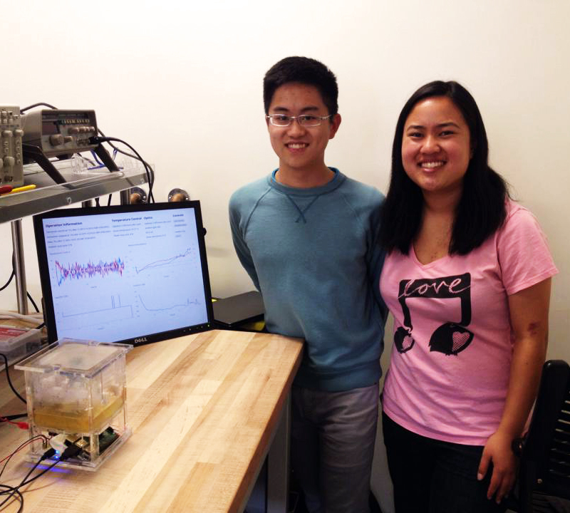
I created this fermentor with Jessica Lam for the BIOE 123 course (Biomedical System Prototyping Lab) in Winter 2015. In this class, I learned about principles for designing a complex system to meet technical requirements, creating system and subsystem specifications, and designing verification and validation tests. I also developed skills in rapid prototyping with Solidworks, 3-D printing, and laser cutting for mechanical subsystems and breadboarding for electrical subsystems. Using these skills, we designed, built, and tested a small Arduino Micro-controlled fermentor for growing E. coli engineered to produce a purple chromoprotein. Per project requirements, we successfully automated temperature control, aeration, mixing, and optical measurement of bacterial culture growth progress. As our project extension, we designed and implemented a live web interface for remote monitoring and control of our fermentor, hosted on a Raspberry Pi. Our final deliverable was a working, self-contained fermentor that served a web page over Wi-Fi with which clients could communicate in real time.
Mechanical Design
For our fermentor, we designed a system featuring proportional temperature control of vessel contents, along with OD and green absorption measurement. Our design met the requirements provided to us to maintain temperature to within 1 °C of the target of 37 °C for optimal E. coli growth, along with measurement and logging of culture growth and protein production for a 200-300 mL E. coli culture.
Vessel Design
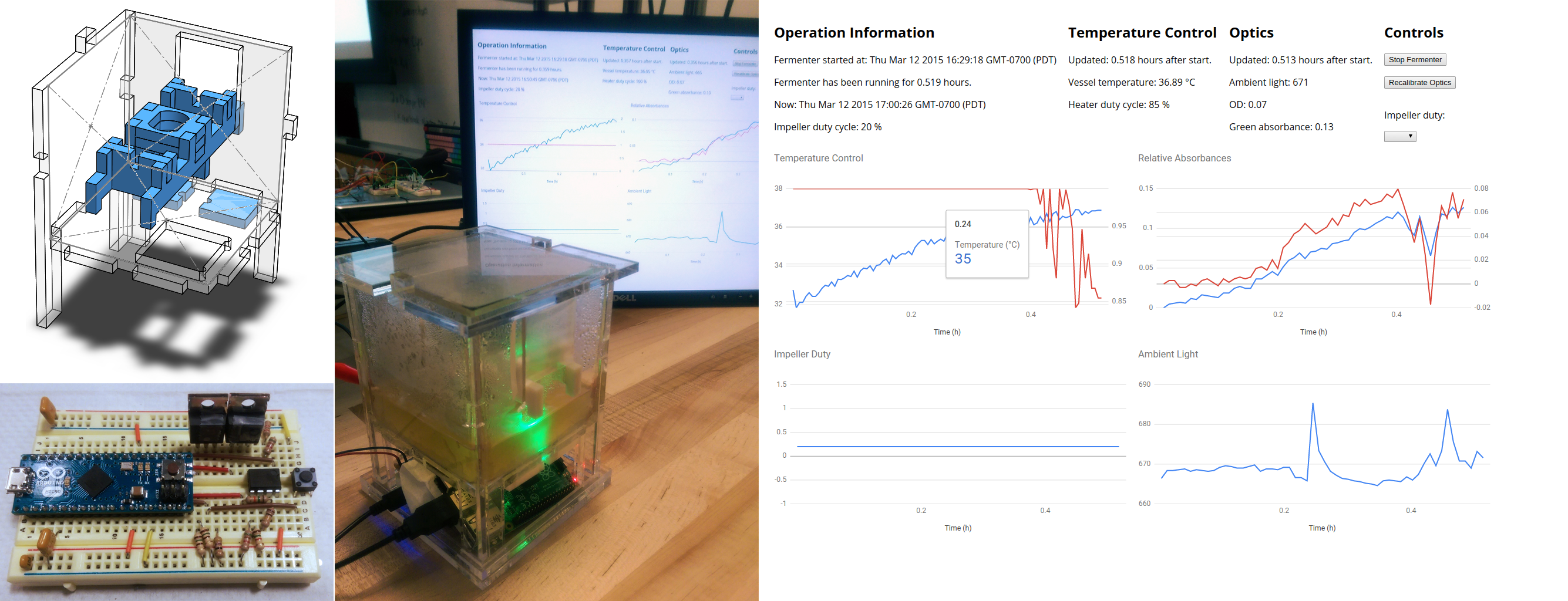
We used Solidworks to design the majority of our vessel as an assembly of 0.25” laser-cut acrylic pieces to be epoxied together into a water-tight body. All acrylic parts were cut out of two 12” by 12” sheets. Part designs and assemblies can be found here. We chose to contain the E. coli culture as a wide, shallow pool in order to maximize oxygen diffusion between the culture medium and the air inside the vessel body.
We made a square hole in the bottom of our vessel body to fit a Peltier cooler used as a heating element. We added notches to the vessel walls to assist with alignment during the epoxying process. We also added notches to two walls to constrain placement and allow ergonomic removal of the lid.
We designed legs under the vessel to create space for our electrical components and our Arduino. We added large holes in the front and rear walls of the vessel to allow for ventilation of vessel contents. For our final vessel assembly, we covered these holes with an oxygen-diffusion membrane to minimize microbial cross-contamination.
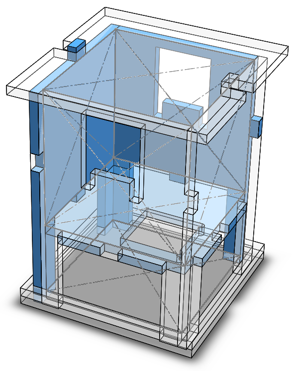
Vessel body design in SolidWorks for laser cutting. Plates highlighted in blue have other components in front of them.
Mechanical Subsystems
We designed a pair of rails with modular mounting plates to allow for addition, replacement, and removal of electrical and electromechanical components, including the impeller motor, the temperature sensor, and the light sensor. These pieces were also designed to be laser-cut. The mounting plate for our light sensor featured a light tube design using the optical properties of acrylic to increase its sensitivity to illumination from red and green LEDs mounted under the vessel body.
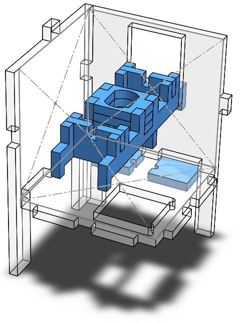
Modular component rail design in SolidWorks for laser cutting. Plates highlighted in blue are the modular component rails and the mounting plates for specific components. Most components are press-fit onto the rails, while small mounting plates for light sources are taped under the vessel floor.
Due to last-minute breakage of the laser cutter used by our course, all of our subsystem parts were 3-D printed except for our light sensor mounting plate.
We designed a four-blade pitched blade impeller to mix our vessel contents. We settled on this design to ensure both axial and radial flow in the vessel contents, given the shallowness of our vessel fluid. Because our motor was epoxied to a carbon-fiber shaft, we designed the impeller as a two-part assembly. Our shaft would be epoxied to the inner part, which would transfer torque to the replaceable outer part. Both parts also featured a hole through which a wire could be threaded, preventing the outer part from unintentionally slipping off the inner part. However, our 3-D printed ABS components press-fit into each other and onto the motor shaft, removing the need for epoxy or wire.
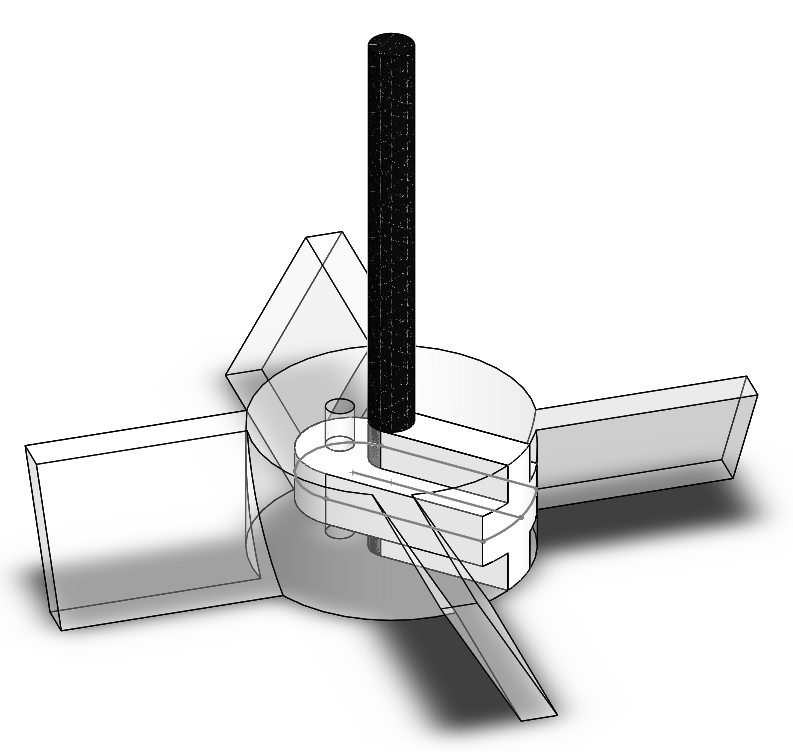
Modular impeller design in SolidWorks for 3-D printing. The black shaft is made of carbon fiber, the white inner piece is made of ABS, and the transulcent white outer piece is also made of ABS. The inner piece is intended to be epoxied permanently to the shaft, while the outer piece can be reversibly secured to the inner piece by a hole through which wire can be threaded. The design of the inner and outer pieces prevents damage to the components by centrifugal forces while maintaining interchangeability of impellers with different blade designs.
Electrical Subsystems
We heated our vessel contents using a Peltier cooler provided to us by course instructors. The cooler was to be used to maintain a temperature difference between its two sides; the hot side would be in direct contact with the culture medium, while a heatsink would be mounted to the cold side to take heat from air ventilated by a small fan. Our Peltier cooler, its accompanying fan, and our impeller motor were controlled indirectly by the Arduino through n-MOS power transistors. The Peltier cooler and the impeller motor were driven through the Arduino pins with pulse-width modulation.
Because the power transistor for the Peltier cooler became incredibly hot while the Peltier cooler was active, we mounted it to the heatsink attached to the cold side of the Peltier cooler. Thus, we could divert waste heat from the power transistor into the Peltier cooler and simultaneously prevent the power transistor from burning users by accidental skin contact.
We designed a temperature-sensing circuit using the LM34 and operational amplifier provided to us. We decided to implement noise filtering in software. Similarly, we designed a circuit to measure red and green absorbance of vessel contents using the LEDs, phototransistor, and operational amplifier provided to us. This circuit used a 10 Hz low-pass filter to attenuate high-frequency noise from ceiling lights, and we implemented filtering of low-frequency changes in ambient light in software by taking measurements of ambient light using our phototransistor.
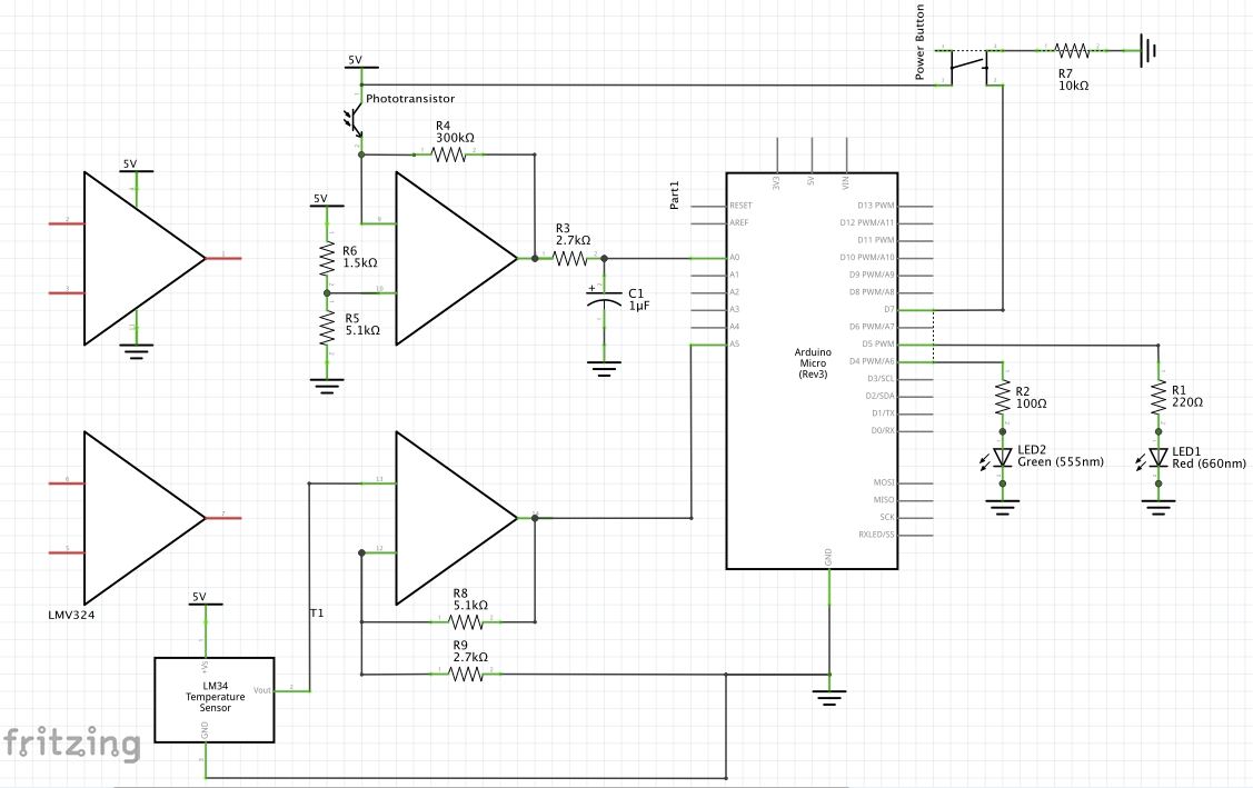
Schematic of vessel sensing circuitry. Two op amps are used for temperature and light sensing, respectively. A single phototransistor is used for measuring absorbance in two different wavelengths from independent LEDs by low frequency time-division multiplexing.
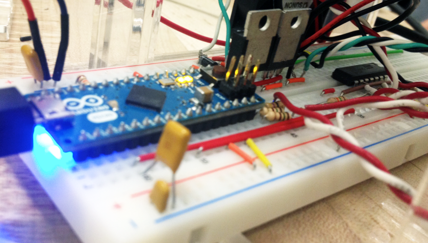
Breadboard layout. Note the addition of MOSFETs to drive the impeller motor and Peltier cooler, respectively, and the addition of wires leading to sensors and actuators mounted in the vessel body.
Finally, we added a tactile button to be used as a single-press on/off switch for fermentor operation. Button presses would be detected and handled in software.
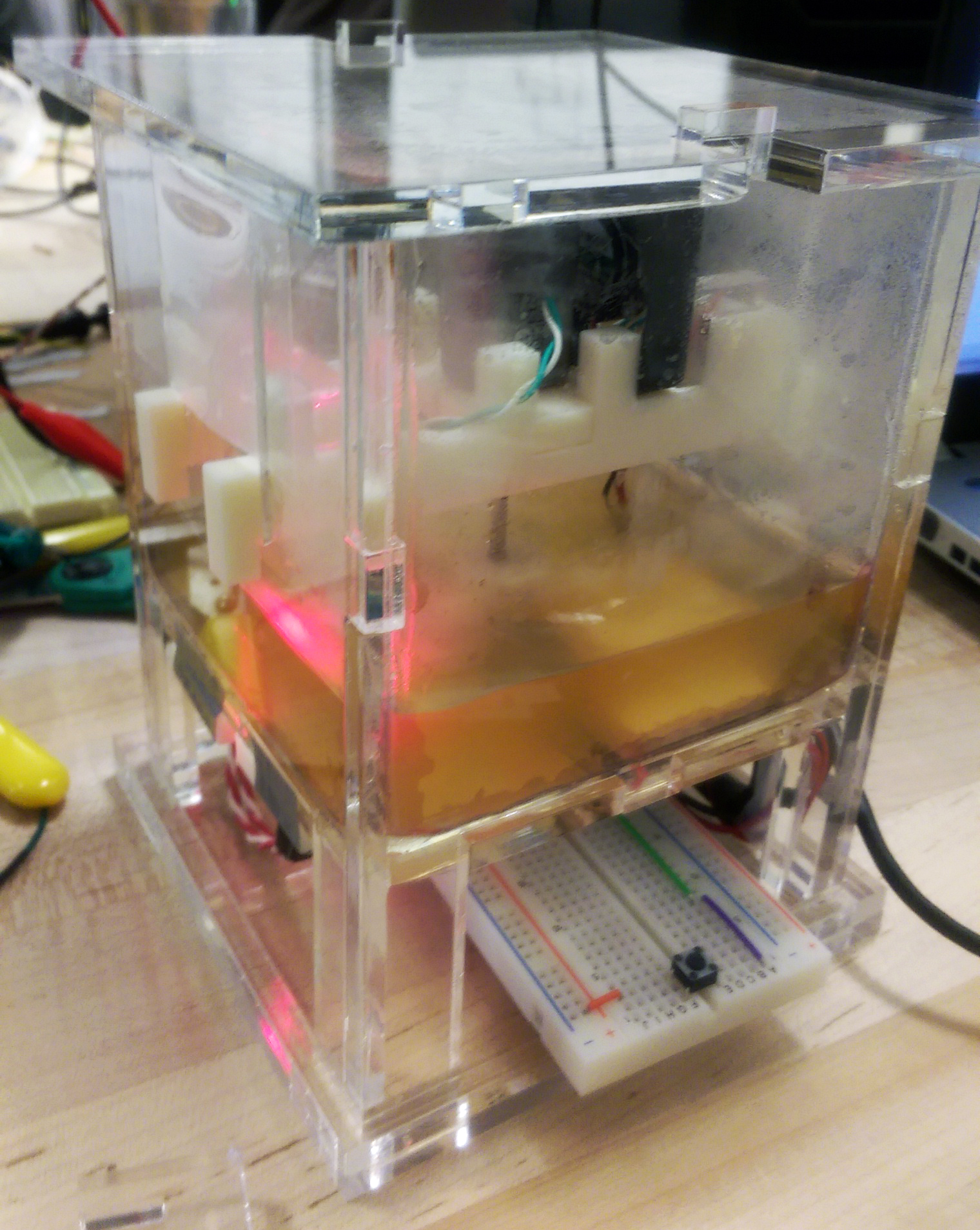
Breadboard under the vessel, with easily-accessible tactile switch near the base of the vessel.
All of our circuitry fit into a breadboard underneath the vessel body.
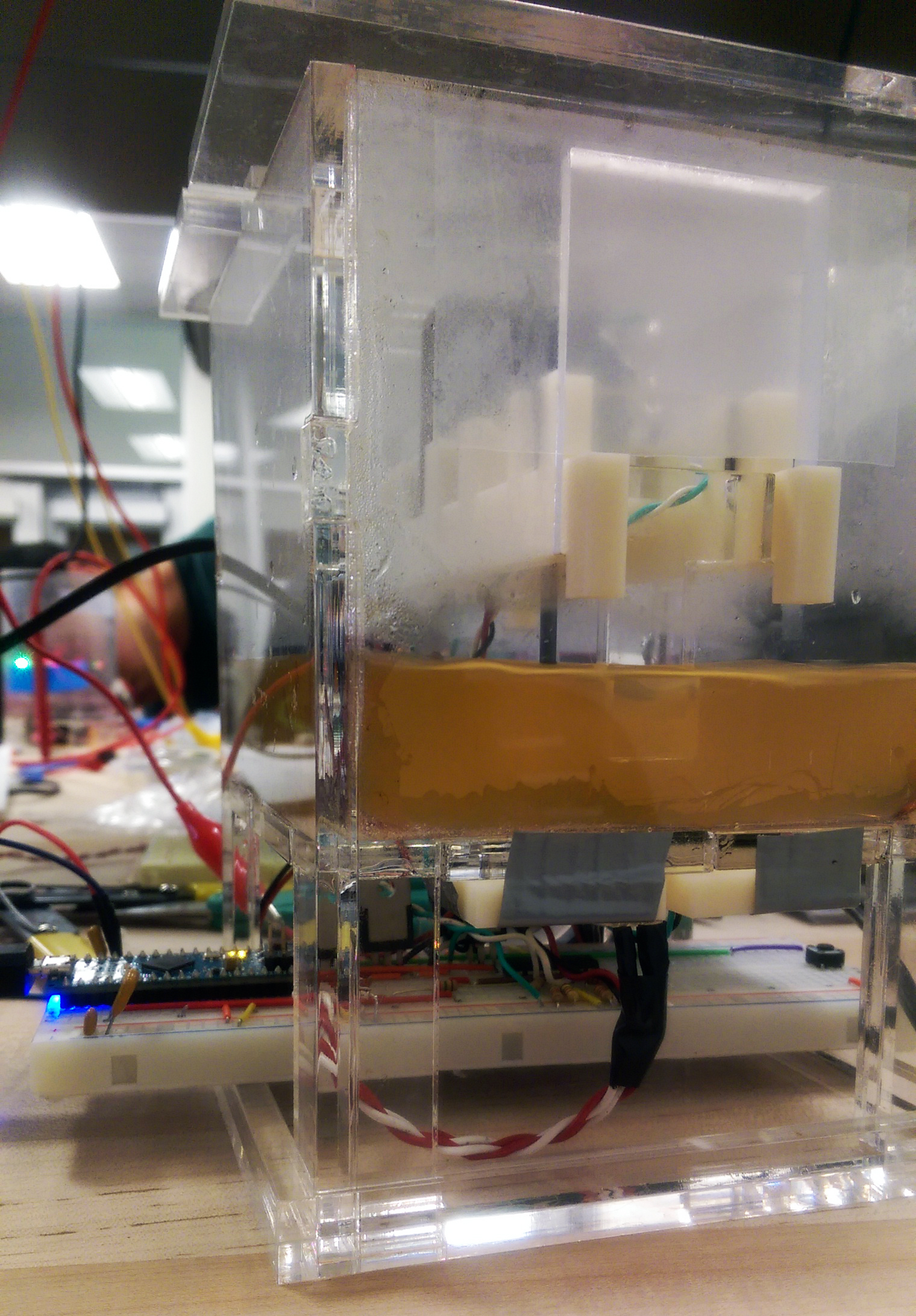
View of the underside of the vessel, with the breadboard resting on the base of the vessel body.
Testing
Throughout our iterative design process, we produced specifications and verification tests for individual subsystems. We then performed integration tests as we assembled subsystems together. Finally, we performed validation tests, culminating in a trial run of our fermentor.
For our trial run, we wrote a MATLAB script structured around an event loop to allow starting and stopping of fermentor option by the press of a small tactile button. We verified high yield of the purple fermentation product after a 24-hour growth interval. However, because the laptop running our MATLAB script automatically restarted in the middle of the night to install updates, we could not obtain a full log of the culture’s protein production progress. This motivated our project extension, to allow control of the fermentor by a small and stable Raspberry Pi single-board computer.
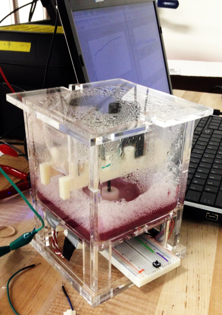
The fermentor successfully enabled the bacterial culture to produce high concentrations of the desired purple chromoprotein.
We also optimized the breadboard layout of all circuitry to fit on a single half-size breadboard.

The optimized breadboard layout. Not pictured are cables to the various sensors and actuators.
Software Subsystems
For our project extension, we chose to control our fermentor with a Raspberry Pi single-board computer. All code can be found on our project’s Github repository.
Device Control
We wrote a multithreaded Python application with the Python Arduino Command API to control the fermentor’s Arduino from a Raspberry Pi connected by the Arduino’s USB Serial interface. This application routinely measures the E. coli culture’s various properties in separate concurrent threads of execution, because many samples are taken over extended intervals per measurement for noise filtering. This application also logs measurements and actuator control data and exposes it for use by other threads. We chose to host our application on a Raspberry Pi connected wirelessly to the internet to make the entire fermentor a mostly self-contained package.
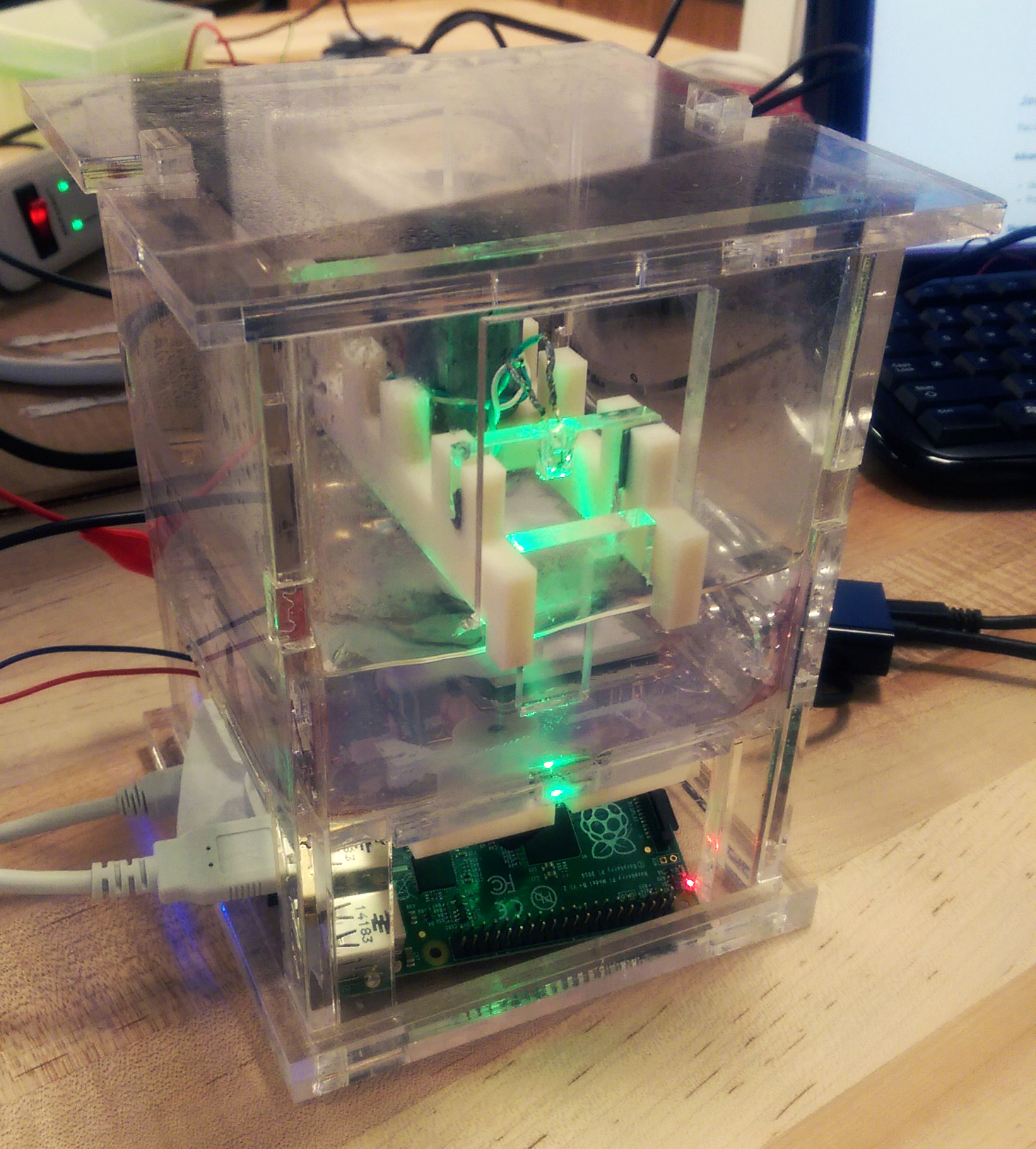
The Raspberry Pi board fit entirely inside the fermentor package, though space was limited. A USB cable connecting the Raspberry Pi board with the Arduino board sticks out on the left. Otherwise, the only components entering the vessel body are power supply cables.
Web Interface
We then wrote a simple Flask web application to allow the Raspberry Pi to serve a web page with information about and user control over fermentor operation. We used Flask-SocketIO with Socket.IO and jQuery to implement frequent live-updating of the web page with real-time fermentor information. We used Google Charts for client-side rendering and updating of plots of fermentor information.
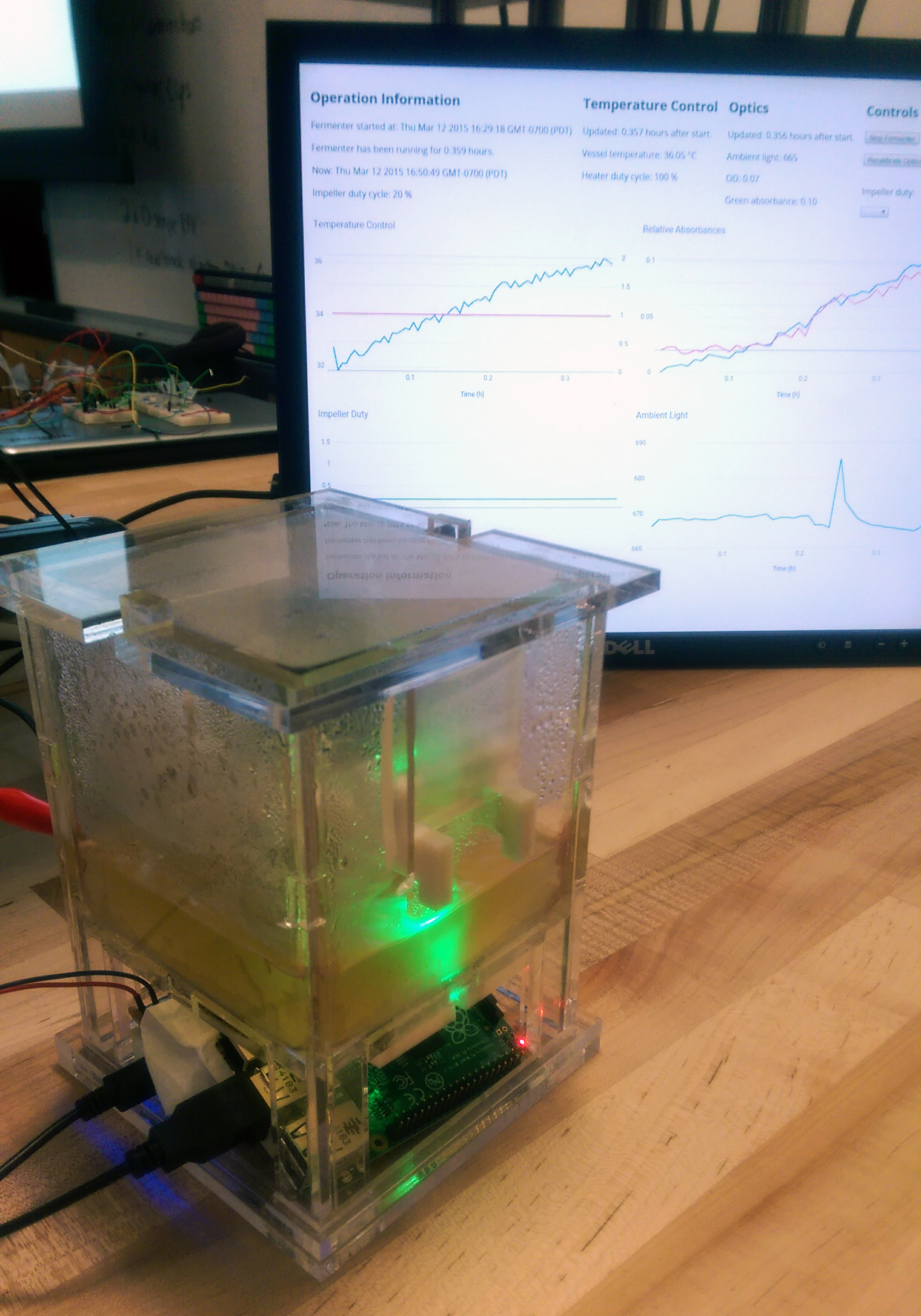
Fermentor vessel in front, and a display connected to a separate laptop behind. The display is not connected to the vessel, demonstrating the ability for the vessel to be controlled remotely.
Interface Screenshots
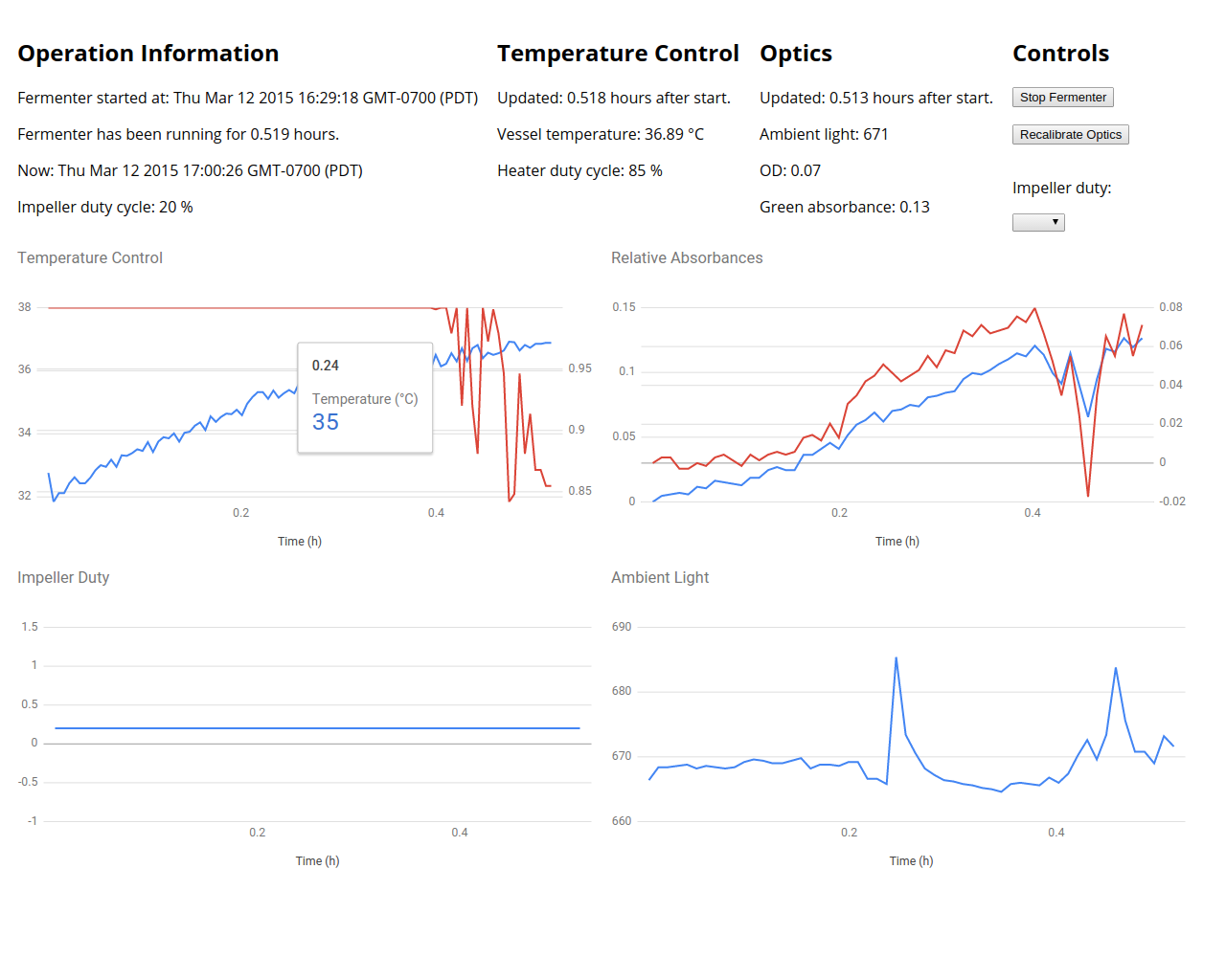
Temperature control logging is shown under the "Temperature Control" section. A hover element displays the temperature and heating element duty cycle at the specified time. The blue curve displays the temperature of vessel contents, while the red curve displays the duty cycle of the heating element.
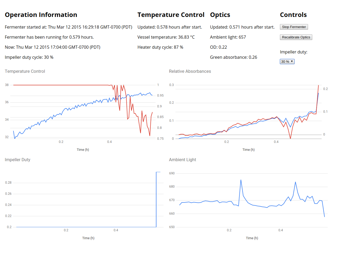
The rotational speed of the mixing impeller can be manually overridden in real time. Note that the impeller duty under the "Controls" section has been adjusted to 30%, and the blue curve under the "Impeller Duty" section has accordingly increased to 0.3.
Conclusion
After completing both extension milestones in a marathon 36-hour coding and debugging session, we presented our project extension to our classmates, instructors, and course assistants. We then demonstrated it to classmates and other professors in our course’s open house session.